A quick lookup at http://www.searspartsdirect.com/cooktop-repair/error-codes/kenmore-790-mode-linduction-cooktop-error-codes.html says "low voltage output from the 12 volt power supply on the filter control board". A look at the Q&A for the model shows some other people have had this problem too..http://www.searspartsdirect.com/model-number/79042800500/0583/0121040.html?searchType=modelSearch&q=790.42800500&searchTerm=790.42800500 (this one has some decent diagrams). The suggested replacement is a $533 filter control board, http://www.searspartsdirect.com/part-number/5304454971/0022/628.html?pathTaken=partSearch. With this being about half-the cost of a new unit and nothing to lose, we decided to tear into it Christmas eve after lunch.
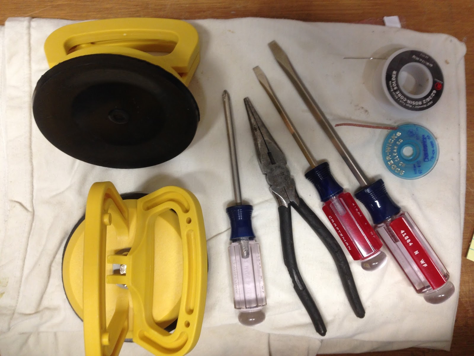 |
| The tool set to tackle this one. |
It's not immediately clear the best way to get into this thing, but I have to admit that it is made to work on. With the unit glass side down, open the wire connection cover and disconnect the wires and the the black cable hold. At this point you can also remove the bus bar jumpers (copper) and all screws and set aside.
Next remove the black vent cover on the front edge and the sheet metal screws around the perimeter (10 or so) once you have them all out, the galvanized steel rear cover should lift off easily with the wires and pigtail still attached. Gently remove the three soft fiberglass insulation pieces and the fiber board piece covering the electronics region and set these aside so they are not damaged.
Holding both the glass and aluminum inner section flip the entire unit over so it is glass side up. Now gently lift the glass piece straight off (it is not adhered, yeah!). This exposes the induction coils.
 |
| The induction coils. |
The front button control board can be removed by sliding off the X5 connector, and the coils detached by unscrewing the leads and unplugging the temperature sensor wires. Once the coils are removed, gently lift off the fiber insulation blanket.

Remove the screws attaching the aluminum support plate to the electronics case underneath.
 |
| The electronics guts. The Range Noise Filter board is at top right. |

After removing all the wires connected to the board, there are two tangs on the left edge to release the board, lift it up, and slide it out of the rear screw connections. (You did remove all the screws, didn't you).
I took the board to the bench and after a trip to the local Radio Shack, had two new capacitors at a whopping $1.50 each. These can be removed from the board with a low wattage soldering iron, and alternately heating one lead and wiggling the capacitor away from the heated lead to "walk it out" of the board. Once removed, use some de-soldering wick to suck up the old solder and open the holes for the new ones.

Place the new caps, getting the polarity correct!, the board is marked with a "+" and the caps with a
"-". Solder them in and reassemble the cooktop.
We noticed too that some of the induction coil lead fork connectors were splayed from over tightening in the factory. These were straightened before reassembly. Make sure all coil connections are a tight snug, but not overly so.
Put everything back in the reverse order of disassembly, turn on the breaker, and test it out with a pan of water and PowerBoost. No more error "32". About 3.5 hours including a run into Radio Shack for the capacitors, and $3 in parts. Maybe $35 in tools if you don't have a soldering iron and de-solder wick.
