Sunday, July 15, 2018

Master Forge gas grill rebuild - rusted bottom pan

It must be part ingrained in the male American DNA, to make due with that $99 gas grill until you can drop several hundred on that shiny stainless monstrosity of a backyard monument we call "the grill".  I fell victim to the urge about 7 years ago when the previous one rusted through the carbon steel burners and starting throwing flame to the rubber fuel line on top of the propane tank.  Luckily this didn't end how you might imagine, I saw the errant flame shortly after lighting and shut it down quickly...

My monstrosity.

I went for the "all" stainless Master Forge from Lowe's, a 60,000BTU (the same output of the heat pump that conditions our entire house) 5-burner 15x30" cooking area with rotisserie and side burner.  After 3 hours of assembly, stacks of sheet metal and hundreds of tiny screws, it was together!


What's left of the bottom catch pan
Flash forward 7 years.   A grill cover has kept it quite good looking on the outside, but the inside was slowly rotting away.  I discovered that the "all" stainless didn't extend to the "all" part.  The catch pan/drip tray was getting quite see-through, and after a few instances of shutting the lid too hard and realizing there was a cascade of rust chips onto my food, I wasn't ready to chuck a $500 grill or pay replacement parts for the same crappy quality parts.


Stainless was obviously plated mild steel
A great go-to place for repair materials of all kinds (https://www.mcmaster.com), I ordered some sheets of 304 stainless to fab some replacements for the catch pan and inner lid shield.  

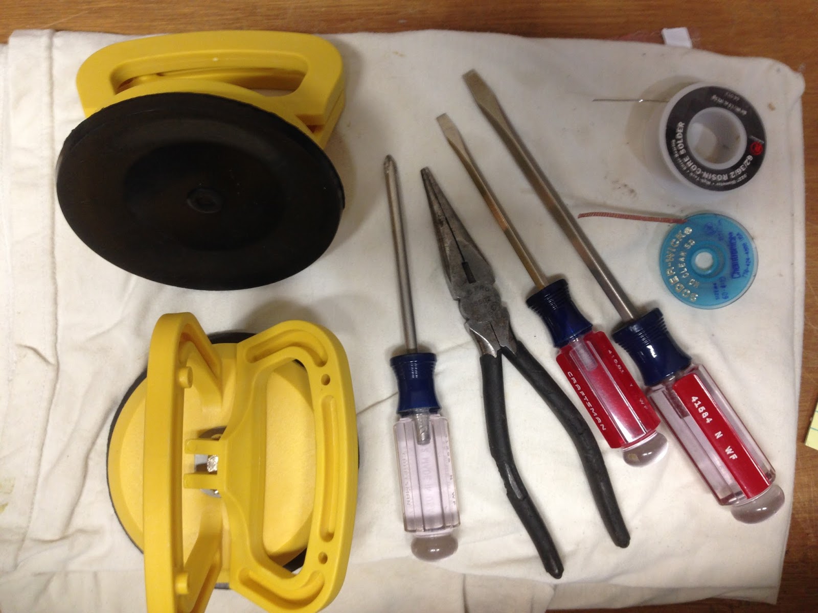
The new catch pan was two sheets of 18x18x0.036", cut to 16.5"x18", then creased to provide some stiffness.  I cut out a 0.75" bit out of two corners then folded up three edges 0.75" to provide a lip and pan stiffness.  Originally, the 0.036" seemed was too thick to bend, but a 3" offset seamer like https://www.hardwareandtools.com/wiss-ws4-seamer-hand-offset-3-inch-daaa-0019.html did the job to fold up the lips.  Once folded, the 3/4" lip was placed in the vise and hammered to set a good 90 degree angle on the metal.  The mounting holes at the left and right edges were measured and drilled on lip to hang the pan.  I placed some 2x6" pieces on the drip tray guide rails to space up the drip pan and make the pan edge level across the grill.  Once set, I drilled four 1/8" holes in the overlap of the two pan halves for pop rivets to secure them together.
New two part drip pan for the grill, installed with stainless tee nuts and machine screws

The inside lid of the grill was just as bad.  After drilling out the two hinge bolts that were completely rusted solid,removing the lid from the grill and the thermometer from the lid, there were a total of twenty 1/8" rivets to drill out.  The plated steel inner lid was a piece of sheet metal 24.5" x 33.25", I opted to go with the 24" width from the 24x36x0.024" 304SS panel and forgo the extra two bends at the front that put a 1/4" jog in the sheet.   The panel has slots front and back to allow air to circulate along the inside of the lid, these were replicated with a 3/8" drill and a cut-off saw, three along the front and and three in back, that were double the width of the original slots.

After slotting and drilling the front and rear rivet holes (using the old liner as a template), I replicated the front and rear bends and rear lip to attach to the grill cover.  Final step was to transfer the holes for the thermometer and it's surrounding standoffs.  Attach the standoffs to lid fit the new inner lid inside the outer lid, and continue riveting it back together with 1/8" SS rivets.  A final run down to ACE Hardware to get new 5/16"-1" lid hinge bolts, put everything back together.

A brand new grill that will hopefully last for another 10 years, for about $100.

Friday, May 11, 2018

DragonX LED light bar - lights out

DragonX 4 Bar LED mobile DJ Stage Lighting Packages/Portable Par Can Kit Gig Spotlight Bar Set/ Sound Activated Wash Flex Light Party System


Cracking the lid
I purchased this last year for my son's school to use in productions with good result.  This year during practice, the light tree was knocked over after it had been on for an hour or so and when it hit the floor, two of the four light pods went out.  What is this, an incandescent bulb?  No, just some poor engineering.

After I found out about the accident, I brought the pods home and opened them up, six screws around the ring and three on the front plate (the center one can stay in as that holds the lenses into the support ring.
Inside the box is quite straightforward, there's a single layer flexible printed circuit board (FPC) bonded onto a 2mm aluminum plate, and 5 wires coming in from the light tree with a GND, +12v, and RGB signal wires.  The circuit is three parallel PWM circuits for each of the RGB, you can see the power transistors and inductors quite easily.


In not too much time, I discovered the cause of the blackout, the LEDs had been dislodged from the respective traces on the FPC (LED1 for instance).


On looking at the LED package, it's quite hefty with a large metal back for heat sinking.  I realized the FPC had holes cut underneath the LED to thermally bond to the aluminum plate for a heat-spreader.  Then I discovered what had happened.  With little to no heat-sink compound, the LED package had no place to dump heat other than through the leads, and being a thin FPC, there was not much copper in the traces to pull away the heat.  After some period of operation, the LED package go hot enough to MELT THE SOLDER, and when it fell over, the weight of the lens package just above was enough to dislodge the LED in the crash.

I had some Arctic Silver 5 thermal compound around from a recent computer CPU replacement, so after a small dab of that, reset the LED and soldered it back in.  If it came completely off, I found a quick check of the LED with a diode check meter was enough voltage/current to just light the RGB emitters inside and verify polarity/operation.

Once back together, I powered it up and found I was still missing blue on that lamp.  Closer inspection of the circuit, I found an open between LED1 and LED2 on the FPC, so I soldered a wire jumper directly to the LED lead to fix the trace.  I suspect the long high-temp operation may have dissolved the FPC copper trace into the solder bond and what looked like a reasonable re-solder joint was not.

Repaired DragonX light bar


Saturday, December 23, 2017

iPhone 6 slow after iOS 11 update?

As you've probably read from several sources and Apple's own admission, they've put in limiters in recent versions of iOS to protect the battery from overheating and phone shutdowns from voltage drops.  This "feature" is slapping a governor on the phone processor by means of limiting is max operating frequency, and in some cases making the phone painful to use.

credit https://www.consumerreports.org/smartphones/does-your-smartphone-battery-die-way-too-fast/

After a recent iOS update to my wife's iPhone 6 (about 2 years old) and my recent 7 purchase, the performance discrepancy was noticeable.  A couple downloads confirmed that the iPhone 6 performance issue was likely the result of this throttling, it appears based on the computed remaining residual design capacity.  The hit was significant, from these screen shots of her phone before the battery replacement.  Down at 88% design capacity, the phone was already throttled down to 1127MHz or even as low as 839MHz.  (shots taken from "Battery Life" by Elinasoft, and "CPU DasherX" by GreenGames Studio.


Luckily, there was a very easy solution to this.  iFixit, https://www.ifixit.com/Store/iPhone/iPhone-6-Replacement-Battery/IF268-002-4  I have to say this is the first time I've used their products, but it won't be the last!   For $19.99 you can buy a new battery, but for $5 more they send you the whole toolkit to do it yourself and have a great online guide
https://www.ifixit.com/Guide/iPhone+6+Battery+Replacement/29363

While it was a little nerve-racking cracking into a perfectly working iPhone, the guide was right on for time, it took me about 25 minutes start to finish (4:02-4:39 by screen shots).  Getting into the phone with the included suction cup was straightforward after I figured out the techique, holding the phone edges with a middle finger and thumb, and pulling the suction cup handle with an index finger leaving the other hand to work in the plastic spudger with the other hand.  I found I did not need to remove the screen and its connections at all, greatly simplifying the process; just taping the screen up to a can of DustOff to hold it open while doing the battery work.  The battery plug is difficult to remove and hard to align the new one, but manageable.  I also found the "3M-esque" Command strip battery hold-downs quite interesting.   Starting to pull with the tweezers, but then grab with a finger to prevent tearing, I was able to remove both without incident.  A slow gentle pull gradually released them, and maybe a slight wiggle back and forth off axis-sped it along, both came off cleanly.

New strips and new battery in, close the phone, and boot with a hard reset (home + power).  The phone came up and back to full CPU frequency.  I followed the recommended drain to <10% and charge fully, which resulted in a reported battery design capacity down 10mAh 1800/1810 (99%), but CPU still at full frequency.


Awesome $35 upgrade (with shipping cost) for a $500 phone!

Is it worth a class-action lawsuit to Apple, absolutely not.  Should Apple be more transparent about slowing down aging phones, the reasons behind it, and better solutions, absolutely yes.

Tuesday, December 27, 2016

Kenmore Elite Model 790 (790.42800500) Induction Cooktop circa 2006 - Error 32

My wife and I noticed over the past couple months that every so often when turning on PowerBoost setting for the cooktop the power to the unit would start to flicker and with all the burner LED status lights flicking on and beeping, followed by a "32" in the timer window and a power off.  Not good.  We love the induction cooktop and weren't ready to give up on it.

A quick lookup at http://www.searspartsdirect.com/cooktop-repair/error-codes/kenmore-790-mode-linduction-cooktop-error-codes.html says "low voltage output from the 12 volt power supply on the filter control board".    A look at the Q&A for the model shows some other people have had this problem too..http://www.searspartsdirect.com/model-number/79042800500/0583/0121040.html?searchType=modelSearch&q=790.42800500&searchTerm=790.42800500 (this one has some decent diagrams).  The suggested replacement is a $533 filter control board, http://www.searspartsdirect.com/part-number/5304454971/0022/628.html?pathTaken=partSearch.   With this being about half-the cost of a new unit and nothing to lose, we decided to tear into it Christmas eve after lunch.

The tool set to tackle this one.
We were smart when we installed the thing 8 years ago that we just put some high-density polyurethane foam tape around the edge to seat it onto the counter (marble tile) with no adhesive.  After shutting off the breaker and disconnecting the pigtail whip, I used a tile/glass lifter to gently pull up at one corner and "break the seal" of it having sat in the counter opening for 8 years.  Once it was loose, I attached a second lifter and moved it over onto the island next to the opening.

It's not immediately clear the best way to get into this thing, but I have to admit that it is made to work on.  With the unit glass side down, open the wire connection cover and disconnect the wires and the the black cable hold.  At this point you can also remove the bus bar jumpers (copper) and all screws and set aside.

Next remove the black vent cover on the front edge and the sheet metal screws around the perimeter (10 or so) once you have them all out, the galvanized steel rear cover should lift off easily with the wires and pigtail still attached.  Gently remove the three soft fiberglass insulation pieces and the fiber board piece covering the electronics region and set these aside so they are not damaged.

Holding both the glass and aluminum inner section flip the entire unit over so it is glass side up.  Now gently lift the glass piece straight off (it is not adhered, yeah!).  This exposes the induction coils.

The induction coils.

The front button control board can be removed by sliding off the X5 connector, and the coils detached by unscrewing the leads and unplugging the temperature sensor wires.  Once the coils are removed, gently lift off the fiber insulation blanket.


Remove the screws attaching the aluminum support plate to the electronics case underneath.
The electronics guts.  The Range Noise Filter board is at top right.
Looking at the filter board, my wife immediately noticed "one of these things is not like the other"... One capacitor can was cracked open and showed some corrosion, I noticed a second that was bulged on the top.  These were either side (top and bottom) of the filter torroid in the upper left.


After removing all the wires connected to the board, there are two tangs on the left edge to release the board, lift it up, and slide it out of the rear screw connections.  (You did remove all the screws, didn't you).

I took the board to the bench and after a trip to the local Radio Shack, had two new capacitors at a whopping $1.50 each.  These can be removed from the board with a low wattage soldering iron, and alternately heating one lead and wiggling the capacitor away from the heated lead to "walk it out" of the board.  Once removed, use some de-soldering wick to suck up the old solder and open the holes for the new ones.


Place the new caps, getting the polarity correct!, the board is marked with a "+" and the caps with a 
"-".  Solder them in and reassemble the cooktop.

We noticed too that some of the induction coil lead fork connectors were splayed from over tightening in the factory.  These were straightened before reassembly.  Make sure all coil connections are a tight snug, but not overly so.

Put everything back in the reverse order of disassembly, turn on the breaker, and test it out with a pan of water and PowerBoost.  No more error "32".  About 3.5 hours including a run into Radio Shack for the capacitors, and $3 in parts.  Maybe $35 in tools if you don't have a soldering iron and de-solder wick.

Tachometer needle gone haywire

After several instances of the tachometer on my New Holland TC29DA reading all sorts of strange numbers, I discovered the plastic barrel backing that presses onto the tach shaft was split open.  The plastic is so darn small and thin, a glue-job to reassemble it was unsuccessful.

The whole instrument cluster comes out with two Philips screws, detach the multi-pin connector from the rear, and take in the gauge cluster to the bench.   Remove the Philips screws around the perimeter and separate the cover glass and bezel from the gauges.  Slide off the old needle (mine literally fell off when the gauge was inverted) and grind or sand the old plastic barrel flush.

I prepped a new backing with a 4mm wide brass strip and 2mm OD x 0.45mm wall tubing (about $6 from a local hobby store) that was soldered together to form a new base and barrel to attach to the tach shaft.  Epoxy the new brass base onto the needle and let it cure.  With a pair of diagonal cutters, put a slight crimp in the tube to give it a light press-fit onto the 1mm tach shaft.  BEFORE, you push it on, go back to the tractor and connect the instrument cluster, and turn on the ignition (without starting), this will set the tach shaft at 0 RPM.  Align the needle and press it on.

Turn off the ignition.  Disconnect the the gauge, and reassemble the cluster housing, bezel, and cover glass.  make sure the needle doesn't fall low and end up below the stop inside the bezel.  Put it all back together, turn on the ignition and the tach should come to 0, start the engine and set to idle and it should be at about 600 RPM.

Beats $670 for a whole new instrument cluster... NH doesn't sell just a replacement needle.... go figure.


New brass coupling fabricated out of some 4mm wide brass strip
 and 2mmODx0.45mm wall tubing

Tuesday, November 15, 2016

Kitchen Aid mixer leaking oil?

Getting into holiday cookie season can be tough.  Our 8-year old Kitchen Aid decided to start making noises and leaking oil out of the gearbox.  Before my wife could spend $200+ on a new one, I asked her to look on repairing it.  She found this great video:

http://www.ereplacementparts.com/article/5518/How_to_Fix_a_KitchenAid_Stand_Mixer_That_Is_Leaking_Oil.html

This turned into a good learning experience and a small family project for a Saturday morning after breakfast.  It really is easy to get inside the mixer, following the steps in the video.  We took the "divide and conquer" to remove the old grease which had gelled and lost its oil.  I took the main body a step further by removing the mixing shaft up through the center gear to clean the main gear and below it.

Not wanting to wait for special order grease or finding any food-grade grease locally, I substituted a Lucas Marine Grade (blue) from Lowe's, being billed as environmentally safe and a relatively benign MSDS.  http://lucasoil.com/products/grease/marine-grease

We repacked the gear box, put it all back together.  Works great, quieter, and smooth gear box!  All for about $5.

Wednesday, September 14, 2016

Windows 10 strikes again... BSOD

Just some thoughts I will be catching here as I've struggled through some problems with Windows 10, in hopes that someone else can learn.  This was a Win7 Pro box that was upgraded in place to Windows 10 Pro.  It's a 240GB SSD OS drive (C:) and 1TB RAID-1 data drive (D:, dynamic GPT)

It all started with a failure to launch Adobe PS Elements 11, with a looping activation error, after Adobe support was no help and tried to troubleshoot by enabling the hidden admin account by "net user administrator /active:yes" and I cut him off, I went into some things:
- create a new admin user and launch, no go
- launch with admin privileges, no go
- reinstall from DVD, from HD, re-enter SN or not, no go
- change C: drive permissions, no go
- recurse C: drive permissions/ownership from TrustedInstaller to Administrator account, BAD - Windows 10 would no longer boot (blue screen of roving cirles... and attempt to repair in Windows RE (recovery environment) and repair startup problems, said it couldn't fix then reported a "WDF_DRIVER_VIOLATION" on next boot along with a BSOD
- What I think happened was the Flexnet licensing got corrupted somehow...

So what happened:

  • Download Win10 install via Media Creation tool and place on USB drive.
  • Boot computer with USB
  • Accept locales, at the botttom "Repair this computer"
  • Boot Win 10RE Command prompt
  • Run DISKPART, LIST VOL to see which drives are which (use the right ones below)
  • Image the original Windows drive to a USB attached backup drive, just in case using:

   >DISM.exe /Capture-Image /ImageFile:G:\SSD-whole.wim /CaptureDir:D:\ /Name:"Windows"
100GB on drive went to about 50GB in a .WIM file in <1 hour on USB3.0 backup drive
Manually copy important files, just in case:
   >xcopy /e /c /h d:\users\<username>\ g:\ssd
   >xcopy /e /c /h "d:\Program Files\" g:\ssd
   >xcopy /e /c /h "d:\Program Files (x86)\" g:\ssd
  • Once complete, reboot the computer back to the USB, accept locale info
    • Custom install
    • Delete all partitions on the SSD (including the 10% overprovisioning made for Win7, since Win10 is smarter about SSDs) -- p.s. it wouldn't install anyway since the drive was MBR partitions and not GPT
    • Create a new whole-drive partition, let Windows configure Recovery and EFI and GPT partitions
    • Install Windows
  • Update and reboot as necessary (Windows 10 online activation worked flawlessly to recognize the computer as it was already activated without entering a Product Key)
  • Run Disk Management, for the 1TB RAID set, right-click disk and say "Import foreign disk" for both.  Allow them to re-sync (this took several hours, and let it finish keeping the computer awake otherwise it will restart from 0)  If you interrupt it, you may have to right-click and "reactivate disk"
  • Once complete, on the DATA DRIVE, take Ownership with the new default admin account and remove old admin account permissions (says Unknown - S-1-5-.... from previous installation)
  • Change Settings>System>Storage to DATA DRIVE for all but applications. (didn't work before ownership correction)
  • Install Office (had online subscription and original install ISO, log into MS account to activate)
  • Add offline PST file to Outlook (Open & Export, Open Outlook Data File from DATA DRIVE)
  • Install MBAM, MBAE (have original product keys)
  • Install iTunes
    • launch once, accept EULA, close
    • launch second time holding SHIFT key, point to remote ITL iTunes Library file (all music and stuff still there)
    • Sign-in to authorize the computer
    • Connect a phone to create the C:\Users\<usernam>\AppData\Roaming\Apple Computer\MobileSync\Backup directory
    • close iTunes
    • rename Backup to BackupOld
    • open command prompt in ..\MobileSync directory and run >mklink /J "Backup" "D:\iTunes Backup"  (this creates a symlink junction to put device backups on a data drive, not the SSD)
    • thanks to: http://www.howtogeek.com/164275/how-to-change-the-backup-location-of-itunes-or-any-windows-app/
  • Download/Install other software
  • Restore Desktop and other files from the XCOPY or DISM image.
So far, so good.